ETJava Beta | Java
 注册
登录
注册
登录
注册
登录
注册
登录
去年的时候把games101的课程以及作业完成,但是整个过程比较粗略,也借助了不少外界的力量(doge),于是最近准备抽几天集中再把作业(1-7)过一遍,常看常新嘛 环境配置直接用:https://github.com/roeas/GAMES101-Premake 之前是在虚拟机上 这次用vs也方便一些
有时间也会研究一下大作业
简要分析一下整体的一个绘制流程
首先定义了绘制的视口 同时初始化了像素缓冲区 与 深度缓冲区:
rst::rasterizer r(700, 700);
rst::rasterizer::rasterizer(int w, int h) : width(w), height(h)
{
    frame_buf.resize(w * h);
    depth_buf.resize(w * h);
}
定义相机位置、三角形三个顶点在空间中的位置,三个顶点的索引顺序,注意我这里相机位置和顶点位置设置的都和原来不一样,这里后面再提:
Eigen::Vector3f eye_pos = {0, 0, 0};

std::vector<Eigen::Vector3f> pos{{2, 0, 12}, {0, 2, 12}, {-2, 0, 12}};

std::vector<Eigen::Vector3i> ind{{0, 1, 2}};
然后创建对应三角形的顶点缓冲区以及索引缓冲区:
auto pos_id = r.load_positions(pos);
auto ind_id = r.load_indices(ind);
rst::pos_buf_id rst::rasterizer::load_positions(const std::vector<Eigen::Vector3f> &positions)
{
    auto id = get_next_id();
    pos_buf.emplace(id, positions);

    return {id};
}

rst::ind_buf_id rst::rasterizer::load_indices(const std::vector<Eigen::Vector3i> &indices)
{
    auto id = get_next_id();
    ind_buf.emplace(id, indices);

    return {id};
}
然后就是设置模型、观察以及透视矩阵,最后绘制
绘制部分:
void rst::rasterizer::draw(rst::pos_buf_id pos_buffer, rst::ind_buf_id ind_buffer, rst::Primitive type)
{
    if (type != rst::Primitive::Triangle)
    {
        throw std::runtime_error("Drawing primitives other than triangle is not implemented yet!");
    }
    读取对应的三角形的顶点以及索引信息
    auto& buf = pos_buf[pos_buffer.pos_id];
    auto& ind = ind_buf[ind_buffer.ind_id];

    float f1 = (100 - 0.1) / 2.0;
    float f2 = (100 + 0.1) / 2.0;

    Eigen::Matrix4f mvp = projection * view * model;
    for (auto& i : ind)
    {
        Triangle t;
        转换到屏幕空间
        Eigen::Vector4f v[] = {
                mvp * to_vec4(buf[i[0]], 1.0f),
                mvp * to_vec4(buf[i[1]], 1.0f),
                mvp * to_vec4(buf[i[2]], 1.0f)
        };
        透视除法
        for (auto& vec : v) {
            vec /= vec.w();
        }
        转换到像素空间
        for (auto & vert : v)
        {
            vert.x() = 0.5*width*(vert.x()+1.0);
            vert.y() = 0.5*height*(vert.y()+1.0);
            vert.z() = vert.z() * f1 + f2;
        }
        设置三角形的各个顶点
        for (int i = 0; i < 3; ++i)
        {
            t.setVertex(i, v[i].head<3>());
            t.setVertex(i, v[i].head<3>());
            t.setVertex(i, v[i].head<3>());
        }
        设置各个顶点的颜色
        t.setColor(0, 255.0,  0.0,  0.0);
        t.setColor(1, 0.0  ,255.0,  0.0);
        t.setColor(2, 0.0  ,  0.0,255.0);
        绘制 这里是用线框形式绘制 使用的画线算法是Bresenham
        rasterize_wireframe(t);
    }
}
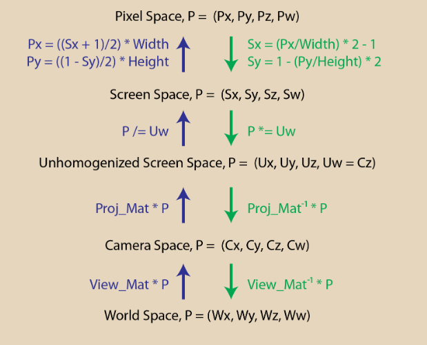
贴一张大致的总结图
重点分析透视矩阵的推导
这里我介绍一下d3d12龙书的推导过程
把点投影到我们的投影平面上 利用相似我们可以得到的关系是(假设投影平面到我们摄像机的距离为1):
为了规范化归一化 我们是要把投影平面\(x\in [-width/2,width/2]\)与\(y\in [-height/2,height/2]\) 转换到[-1,1]的这个平面上,要经历变换:
如果我们使用fov 与 宽高比(r)来表示 则可以转化为:
可以看出我们其实是要对x,y进行两步变换 我们可以第一步先进行归一化变换
同时为了进行透视除法 我们需要存储z坐标,所以在第一步中我们要利用w分量来存储z值,得到的变换过程如下:
之后第二步再进行透视除法:
最后我们还需要对z深度值进行归一化操作 将z值转换到0-1 在上述矩阵中我们可以直接利用 A与B来进行,令近平面上的点深度值为0,远平面上的点深度值为1:
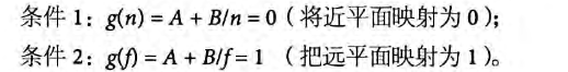
最终的透视矩阵:
注意这里我设置的相机以及顶点位置发生变化:
Eigen::Vector3f eye_pos = {0, 0, 0};

std::vector<Eigen::Vector3f> pos{{2, 0, 12}, {0, 2, 12}, {-2, 0, 12}};
r.set_projection(get_projection_matrix(45, 1, 0.1, 50));
这样设置就不会出现原来三角形倒置的问题了
因为按照原来的设置 z轴是朝外的 近平面原平面都设置为正 相当于相机朝向是z轴正方向 而三角形却在z轴负半轴方向 这样会产生问题
我觉得这样改会比网上那个直接改透视矩阵要简单一些
Eigen::Matrix4f get_model_matrix(float rotation_angle)
{
    Eigen::Matrix4f model = Eigen::Matrix4f::Identity();

    // TODO: Implement this function
    // Create the model matrix for rotating the triangle around the Z axis.
    // Then return it.
    float Cos = cos(rotation_angle / 180.f * MY_PI);
    float Sin = sin(rotation_angle / 180.f * MY_PI);
    model << Cos, -Sin, 0, 0,
        Sin, Cos, 0, 0,
        0, 0, 1, 0,
        0, 0, 0, 1;
    return model;
}

Eigen::Matrix4f get_projection_matrix(float eye_fov, float aspect_ratio,
                                      float zNear, float zFar)
{
    // Students will implement this function

    Eigen::Matrix4f projection = Eigen::Matrix4f::Identity();
    float TanFov = tan((eye_fov / 2) / 180.f * MY_PI);

    projection << 1 / (aspect_ratio * TanFov), 0, 0, 0,
        0, 1 / TanFov, 0, 0,
        0, 0, zFar / zFar - zNear, -zFar * zNear / zFar - zNear,
        0, 0, 1, 0;

    return projection;
}
效果展示:
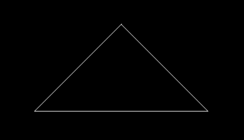
整个代码框架和作业一变化不大
最大的差别就是将之前使用画线算法绘制线框 改为 实际填充像素光栅化 即
draw函数的变化
整个绘制过程如下:
1.找到三角形图元的boundingbox
2.判断范围内每个像素块是否在三角形内(使用叉积判断)叉积得到的是一个三维向量 我们应该使用z坐标来判断(xy平面上做叉积得到的是一个垂直于xy平面的向量)如果三个叉积的结果同号 则说明点(像素块中心点)在三角形内
3.使用面积比例计算得到重心坐标
4.使用重心坐标插值得到三角形内像素点的深度 这里要进行透视校正插值 但是原代码的方法是有错误的 应该使用三维空间中的正确深度值 而不是像素空间被压缩之后的深度值 详细说明见:https://www.cnblogs.com/dyccyber/p/17873365.html 与 https://zhuanlan.zhihu.com/p/509902950
5.进行深度测试
覆盖测试:
这里我直接计算了z坐标 没有整体计算叉积
static bool insideTriangle(float x, float y, const Vector3f* _v)
{
    // TODO : Implement this function to check if the point (x, y) is inside the triangle represented by _v[0], _v[1], _v[2]
    Vector2f v0P(x - _v[0].x(), y - _v[0].y());
    Vector2f v1P(x - _v[1].x(), y - _v[1].y());
    Vector2f v2P(x - _v[2].x(), y - _v[2].y());
    Vector2f v0v1(_v[1].x() - _v[0].x(), _v[1].y() - _v[0].y());
    Vector2f v1v2(_v[2].x() - _v[1].x(), _v[2].y() - _v[1].y());
    Vector2f v2v0(_v[0].x() - _v[2].x(), _v[0].y() - _v[2].y());
    float Xp0 = v0v1.x() * v0P.y() - v0v1.y() * v0P.x();
    float Xp1 = v1v2.x() * v1P.y() - v1v2.y() * v1P.x();
    float Xp2 = v2v0.x() * v2P.y() - v2v0.y() * v2P.x();
    return (Xp0 < 0 && Xp1 < 0 && Xp2 < 0) || (Xp0 > 0 && Xp1 > 0 && Xp2 > 0);

}
屏幕空间光栅化:
这里我使用了4xssaa进行抗锯齿 要建立一个四倍的framebuffer与depthbuffer 依次对每个采样点进行覆盖与深度测试 然后求平均颜色
void rst::rasterizer::clear(rst::Buffers buff)
{
    if ((buff & rst::Buffers::Color) == rst::Buffers::Color)
    {
        std::fill(frame_buf.begin(), frame_buf.end(), Eigen::Vector3f{0, 0, 0});
        std::fill(frame_sample.begin(), frame_sample.end(), Eigen::Vector3f{ 0, 0, 0 });
    }
    if ((buff & rst::Buffers::Depth) == rst::Buffers::Depth)
    {
        std::fill(depth_buf.begin(), depth_buf.end(), std::numeric_limits<float>::infinity());
    }
}

rst::rasterizer::rasterizer(int w, int h) : width(w), height(h)
{
    frame_buf.resize(w * h);
    depth_buf.resize(w * h * 4);
    frame_sample.resize(w * h * 4);
    helper[0].x() = 0.25;
    helper[0].y() = 0.25;

    helper[1].x() = 0.75;
    helper[1].y() = 0.25;

    helper[2].x() = 0.25;
    helper[2].y() = 0.75;

    helper[3].x() = 0.75;
    helper[3].y() = 0.75;

}
void rst::rasterizer::rasterize_triangle(const Triangle& t) {
    auto v = t.toVector4();
    int XMin = std::min(std::min(v[0].x(), v[1].x()), v[2].x());
    int XMax = std::max(std::max(v[0].x(), v[1].x()), v[2].x());
    int YMin = std::min(std::min(v[0].y(), v[1].y()), v[2].y());
    int YMax = std::max(std::max(v[0].y(), v[1].y()), v[2].y());
    for (int x = XMin; x < XMax; x++) {
        for (int y = YMin; y < YMax; y++) {
            int index = get_index(x, y) * 4;
            for (int i = 0; i < 4; i++) {
                if (insideTriangle(x + helper[i].x(), y + helper[i].y(), t.v)) {
                    auto [alpha, beta, gamma] = computeBarycentric2D(x + helper[i].x(), y + helper[i].y(), t.v);
                    float w_reciprocal = 1.0 / (alpha / v[0].w() + beta / v[1].w() + gamma / v[2].w());
                    float z_interpolated = alpha * v[0].z() / v[0].w() + beta * v[1].z() / v[1].w() + gamma * v[2].z() / v[2].w();
                    z_interpolated *= w_reciprocal;
                    if (z_interpolated < depth_buf[index+i]) {
                        depth_buf[index+i] = z_interpolated;
                        frame_sample[index+i] = t.getColor();
                    }
                }
            }
            frame_buf[index / 4] = (frame_sample[index] + frame_sample[index + 1] + frame_sample[index + 2] + frame_sample[index + 3]) / 4;

        }
    }

}
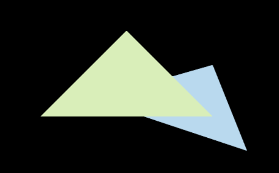
结果展示:
 官方公众号
官方公众号